
UPDATE !! 7th Aug 2019. It works ! Another ESP32 ("TTGO T8 - V1.7") board has been obtained, which has extra memory on it. This allows a larger display (320 x 240 pixel) to be used if desired for other projects. The older ESP32 board detailed below is restricted to a 128 x 160 pixel TFT display.
The 'new' board details are now added here at the end of the page. and build details, Sch, Manuals, Software added 5th May 2020
June 28th 2021: Builders picture added, outboard VFO for FT-7.
| A digital display and VFO for the FT-7™ |
The Yaesu™ FT-7 Transceiver is a product of the late 70's and early 80's, a 5 band HF Transceiver. It uses an Analogue VFO and display. |
It would be nice to 'update' the FT-7 a little by adding a digital VFO using a low cost Si5351™ device and some sort of digital display. We are not talking here about commonly available, simple external displays which just display the VFO signal (with band offsets). The idea here is for a fully integrated (internal) display to replace the analogue one, and also to digitise the VFO itself using the ubiquitous Si5351. |
| Possible ways to add the digital VFO/Display |
Since repairing an FT-7 bought in 'faulty' condition at a Hamfest, thoughts turned to adding the Digital updates as above. Searching the Web found a couple of projects by builders, but lacking in some details. 7-Segment LED display: This is probably one of the easier mods to make in that well understood 7-segment displays can be used. Single or multiple digit displays are easy to obtain on eBay™ for example. To actually fit say, a 6 digit display, to give resolution of 100Hz, displays of around 7.6mm wide for each digit can easily fit into the approx. 50mm wide VFO display window of the FT-7. An Arduino "NANO™" or just the ATMEGA328P™ can easily drive these displays via a MAX7219™ for example, which is the simplest way to multiplex the 6 digits. In VK3, the MAX7219 is only easily obtainable (ie next day delivery) from the international vendors, Element14/Farnell™ but the devices are very pricey, in the order of AUD$16. Ebay is another possible source. I decided to buy an eBay 8 digit display and remove the MAX7219 from it, as the most economical solution for me at least. These displays use 2 x 4 digit devices which are too large for the FT-7 though. I have since found that there is a Chinese made "equivalent" for the MAX7219 for about $2. I have not tried one of these. Here is a draft picture of a test bed 7-segment type display and VFO I will try initially. The PCB is 50x100mm but can be cut into several sections, with the actual 6 digit LED display (bottom of pic) being mounted in the FT-7 dial window area.
APRIL 22nd, 2019:- The above PCB has now been tested with some software based on the work by VK3HN, for his portable SOTA rig. (Summit Prowler IV) I altered his sketch to change the display from his OLED type to my LED display using a LIB obtained on the web. ("DigitLedDisplay") and also implemented band selection using 5 inputs which are derived from the five band switch in the FT-7. One problem found, was the 6 digit LED "3661AS-1" display I ordered from eBay, had a different pin-out to the actual Data Sheet! I had to hand wire the PCB section for the display. Not sure how to get around this problem, as I can only rely on the vendors description and information. It 'might be' that a "3661AS" has the correct pin-out, if one could find such a part on ebay. A nice to have, blinking the digit of the currently selected one being tuned by the Encoder was also done. So far it looks likes it could be integrated into the FT-7 and work to replace the VFO at this point of development. An Si5351 is controlled by the Arduino NANO also and puts out +7dBm. I am yet to determine what actual level is required. This will be easy enough, as the FT-7's VFO output is a connector on the rear of the VFO housing. Just un-plug and measure the levels. Assuming 50ohms perhaps load? You can see my very 1st youtube video here of the board above, working. There are many other possible additions though. eg Memories for favourite fequencies. Clarifier etc. A "better" approach: An incredible FT-7 display, visually, might be obtained using the work of "Tj Lab", whose videos appear on uTube here. It visually emulates the analogue display of the FT-7 almost exactly, plus providing a multi digit display also. He provides information on two versions of display, using OLED and TFT displays. The controller though is well beyond the humble NANO, a very fast Micro is required. In this case the ESP-32/ESP32s™ development board (eBay). Since I have a similar 1.8" TFT display already, I decided to try this approach. His Sketch is incomplete in that no band changing inputs are provided for example as the project was just to demonstrate the VFO in isolation. Initially I will duplicate his work, then see if I can modify it specifically for the FT-7. This approach is overkill of course, and probably more expensive, compared to the 7-segment LED way, but sure has a lot of "wow" factor as you can see! Or "bling" as some may say. CLICK ON uTUBE VIDEO BELOW for the Video by the originator of this code..
UPDATE, May 9th 2019. I have put together a test board to try this sketch out for the ESP32. (see PCB pictures below) I didn't use the same development board version as I couldn't find a source for it. The ESP32 board I did find is only about US$5.50, cheaper anyway. But not all Ports are bought out on this board. (it has 30 pins) I had to alter the port allocation for the Encoder only and do the appropriate change to the sketch #defines. I used D34, D35. The schematic provided by TJ_Lab has to be modified for the ESP32 I used. I compiled TJ's basic TEST code without errors and downloaded it to the ESP32 board. Initially I had problems with this, but found the "BOOT" button needs to be pressed to allow it to work. And work it does, very nicely. Especially nice is the variable speed of the dial, according to the speed of the encoder knob. Brilliant ! The 1.8" display I used is not the exact type specified, but one that does use the same controller chip. Display is about $4 from memory. Different pin-out also. John, WA2FZW, is also working on this project with me. He is the C++ man, I do testing, and some minor code changes. Right now, it's working well as a 5 band (connected from the FT-7's 7 band switch) VFO running 5-5.5MHz and correct dial frequency display for each band, which suits the FT-7. Other rigs could no doubt be accommodated using these ideas. The Si5351 is working well also. Jim, G3ZQC, is another working with the ESP32 VFO. The software also incorporates additions which cater for using a standard cheap mechanical encoder, or a high pulse count, quality optical encoder by changing a 'divide' ratio in the added "config.h" file. In fact, a number of compile time options are provided for.
12th April, 2019:- Mechanical considerations: The display itself should fit into the existing display window of the FT-7. Since we are changing to a digital VFO also, then all of the existing VFO and slow motion dial mechanics are no longer required and can be removed. The VFO knob though is retained to fit onto the digital encoder which will be used to tune the radio now. The VFO itself is contained in a shielded box area which can be fairly easily removed and kept if one wants to revert back to the old VFO, at some later time. The project could also be built as an external VFO although it will be limited, in that, band selection of the VFO would have to be manual. Internal to the FT-7, we can pick off band selection from the rotary switch by freeing up the FIX position. For use on other HF rigs, the builder can interface to unused pins (ports) as required, with suitable software changes. Some method of holding the new Encoder, Si5351 and Micro-controller will of course be needed. See below for possible PCB. Components that I used:- I bought all of the parts for this project from eBay. Rather than give details of the vendor I used, I will show the exact parts in picture form. For the display, search for "ST7735 display" or similar. You will find a number of them but if you look for the type shown here, within that search, it should be OK. The OLED type that TJ tried is very expensive so I didn't buy one of them.
I also found the same display that TJ used on eBay. It just arrived today so I have not tried it yet but can't see any problems. It is however a slightly smaller PCB at 58 x 35mm, than the one above which is 63 x 38mm, but the display area is the same at 1.8".
The ESP32 I used is a little different to that by TJ. It has less pins and cost was about US$5.50. In eBay, search for ESP32 and look for a similar board to this.
There is nothing on the bottom of the PCB except for the pins, so I won't show them. JUNE, 2019:- I have also since purchased from eBay, another version of the ESP board. It has a 4MB "PSRAM" on it and should allow use of larger pixel count TFT displays. It has a different pin-out and is a little larger also. It's about US$15.00 though compared to the $5.50 of the one above. Loaded with identical software and using same Port pins, it works the same. But work on taking advantage of the extra memory for a larger display, is ongoing. Later though, the plan is to use a PCF8574 port expander to free up some pins of the ESP32. To connect to the Schematic by TJ, just follow the pin connections in the ESP32 that I have. You will find though that this ESP32 is missing the two pins required for the Encoder. So, instead of using 16 & 17, use D34 & D35. In the "VFOsys_astep.ino" sketch provided by TJ, you will need to find these lines:-
and change them to
For the optical encoder I used a 360 pulse per turn type. Search eBay for "optical encoder". You will find a number of them similar to what I have. NOTE: TJ specifies a 40 pulse per rotation type of encoder. I actually divided down the pulses from my encoder using a ATtiny85 device (8 pin DIP) with a special sketch by G3ZQC. I won't detail that here for now. Amateurs skilled in programming no doubt could integrate the division into the ESP32 also. See the update above for 9th May 2019, as this facility is in a new Sketch.
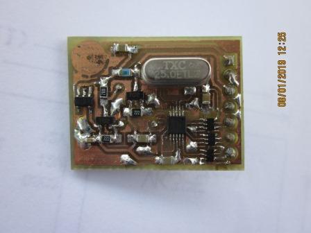
The Si5351 board. There are a number of Si5351 boards available. One common one is that sold by Adafruit Check their web page. No doubt similar ones are also available on eBay although I have not tried them. Most of these boards do not include any DC blocking capacitors on the output so you should add them. My application is for a VFO replacement in an FT-7 and only one of the outputs, covering 5-5.5MHz is required. The Si5351 output is a square wave and I plan to fit a Low Pass Filter (LPF) on the output of mine to better suit the application perhaps. Right now I don't know exact levels required for the VFO signal. UPDATE July 14th 2019:- the existing FT-7 VFO output level is about 120mV rms. I actually have my own design Si5351 board. It's heavily based on the Adafruit one but also includes buffer devices on each output of the Si5351. It's a smaller PCB also. It's now connected to the ESP32 and also the LED versions of this project and working. The Adafruit PCB will also fit my PCB.
My Si5351 board SCHEMATIC IS here. And a picture of the prototype is here. The BOM is here.
Depending upon the facilities you require in your own build, for a particular purpose, you may need to further alter or add to the Sketch provided by TJ. A PCB ? I am currently working on a PCB for this project for my install into the FT-7. It will include the ESP32 board socket, plus the other parts required. The actual display will be connected with a short cable, see below. The PCB arrived on 24th April, 2019. I have loaded it up and tested the ESP32, the Display and encoder. BUT, see later PCB below.
The PCB is 50 x 80mm. NOTE:- it ONLY suits the ESP32 board I purchased, as shown above.
The un-loaded area at the bottom of the PCB is a low pass filter for the output which in the case of the FT-7 is approx. 6MHz filter, so that the output is sinusoidal. For use in the FT-7, only one output of the Si5351 is required so the other 2 outputs are not used. For other projects though, they could be bought out to header pins fitted into the nearby prototyping area. (lots of pads on 0.1" grid at the end of the PCB.)
SCHEMATIC? 24th APRIL, 2019:- This is a draft Schematic. NOTE: It contains some options like TWO different TFT displays (ST7735 controller) which actually connect to the connector "JP3". Some variations for power supplies and also it shows band selection inputs. The actual PCB has some prototyping areas in case of minor changes being required. DRAFT Sch in pdf format The overlay showing values is here. There have been some minor changes to this PCB and Schematic, which I will detail here soon. eg, the 40M band input pin has been moved to avoid a conflict with port D12 which needs to be at logic "low" level at programming time.
Update 14th July 2019 This is the final version of the project. THE new ESP32 BOARD WITH EXTRA MEMORY is the "TTGO T8 - V1.7" . There are a number of TTGO named boards on eBay but the one actually used is shown below in the picture. It's around US$8 - 10, last time I looked. The text "T8 V1.7" is printed on the middle of the PCB.
This board is used on a new PCB design by vk3pe. It's about to arrive in a few days and an actual picture will be shown here then. The new er ESP32 and code changes allow the use of different TFT displays with various controllers. Types with the ST7735 and ILI9341 have been tested. Others may work also but not tested. A small group of us, VK3PE & G3ZQC, but mainly WA2FZW, have developed software for this version with many extra features. Dual VFO's for example. Plus many variations for the actual display content are possible. The picture here is of my customised display with only a single scale. All colours are changeable to suit your preference.
Final text locations & size may vary. Note the cursor under the active tunable digit. This is a picture of the display as setup for my FT-7. The bottom section is blank as it won't be visible in the actual window available.
This is my PCB developed for the ESP32 V1.7 The reason for the angled ESP32 board is there is not enough height available in the FT-7. Also, easy access to the USB port is required for programming. NOTE the picture proportions are incorrect due to my ancient web page Editor.
On the bottom of the PCB is the Adafruit Si5351 module, or equivalent. Plus an RCA socket for the output of the VFO signal to mate with the existing RCA connector in the FT-7. The picture on the left does not yet have the Low Pass Filter parts fitted to clean up the VFO signal. Like all prototype boards, there are a couple of parts that need to be tacked on the back of the PCB. You can just see one in the right hand picture, a leaded resistor. Most parts are SMD. But the board is not crowded so easy to solder them on. See link below (minor mods) THE PCB: Schematic here. NEW August 21st, 2019 (This Sch was used to make the V1.0 PCB above. There were a couple of parts omissions which will be fixed if I ever make a V2.0) See link just below. Bill of Material (BOM) NEW Aug 2nd here (xcell) Does not include ESP32 board or Display. The PCB Showing parts fitted by value. Click here. Aug 21st 2019 The PCB requires some minor mods. Click here for information. Gerber Files. .....later...... Sketch, Software & Manuals.See John's Github here NEW 5TH May 2020 Installation hints. Please note that this project is for experienced constructors only. Information will be placed here, but assumes a certain amount of experience in reading schematics, the Arduino environment and actual construction of a PCB plus modifications to fit it into the FT-7. Any reasonable help will be given to those who want to try this, but most details should be self evident to experienced constructors. See also pictures of the installation in VK3PE's FT-7. The project is not limited to the FT-7. It's been designed with simple customisation in mind, to be usable on many VFO projects. The software has many variables to cater for other uses but that is left to builders. In fact, later, it will be installed into a Yaesu FT-620, an old 6M rig from the 70's. In this project, only one output of the Si5351 is used, but the PCB has provision with a couple of holes to extract the two other signals if needed. Some provision is already in the software to cater for this. Since not required for the FT-7, no further info is provided.
INTERCONNECTION GUIDE: Click here for a drawing of the connections to the PCB into an FT-7. Other rigs will be similar but it's up to the builder to work this out as I have no knowledge of other rigs.
These are some preliminary pictures of how the new VFO was installed.
As you can see above, the original VFO has been removed. A simple aluminium 'L shaped chassis' has been made to hold the new VFO board and also the Tune Encoder which can be seen to the right side of the pictures. The bracket in my FT-7 also holds the encoder for tuning but a better Idea is to mount this encoder directly to the front panel. The PCB is fitted on 25mmtapped spacers as can be seen. The original Clarifier control (pot.) was removed and in it's place another rotary encoder was fitted, with an extension shaft so it is same length as the original Pot. This is needed so the original knob can be used in the same location. The Clarifier "ON/OFF" is now controlled by the Encoder which has a push button switch built in. It's not mandatory to fit the Clarifier. Personally I have rarely foud the need for one in this age of accurate displays on most modern rigs. The Tune encoder also has a switch which can be used to select tuning increments of 1KHz, 100Hz and 10Hz. A short red line under the appropriate digit indicates which increments are being used. They are visible in the screen shots below.
Here is a shot showing all of the bands still controlled from the original band switch. There remains some work to black out the unwanted area of the TFT display. NOV 2019:- NOTE, the pictures may not show current display as it was found with a little re-location of sections of the screen, a VFO "B" could also be fitted in. (This would require an additional switch be fitted "somewhere" to alternate between them. VK3PE has elected not to implement this feature at this stage.) Thats the beauty of this sofware, many variations are possible to suit your own needs. All easily changed in the "config.h" file. The red line under a digit shows which digit is the current one for tuning. Pressing the knob changes this from 10's, 100Hz or 1KHz. (Some black tape was fitted to unused areas of the TFT display after these pictures were taken, to make it nicer to view.)
TFT fitting: The TFT used is mounted behind the opening in the FT-7 front panel. Since the opening height is less than the actual TFT display height, the formatting of the TFT was altered to use only about the top 2/3rd of the display. The very top few pixel rows are also obscured. The TFT is mounted on a home made plate made of aluminium 1.2 or 1.6mm thick. It uses the existing mounting holes in the chassis that were used for the old VFO. The actual screws holding the TFT should be countersunk types and mounted from the rear. The TFT is then mounted on these screws with some short spacers, then a holding nut. Click HERE for upto date drawing.
Below is the output of the VFO. Note that the Si5351 square wave is converted to a nice sine wave by the on board low pass filter. The levels are virtually the same as that from the original VFO. picture soon
Builders pictures:-
vk3pe
Page created on March 18th 2019, by VK3PE and last updated on June 28, 2021 The information on this page is presented in good faith. No warranty of any kind is given that other builders can achieve the same results as experience may vary. The author has no affiliation with any trade names or companies that maybe shown on this and other pages.
|
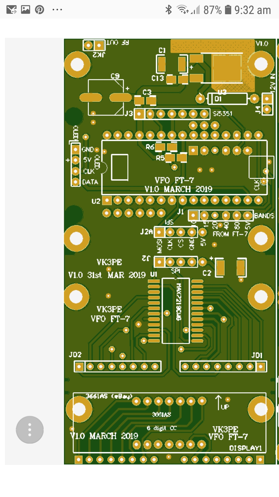
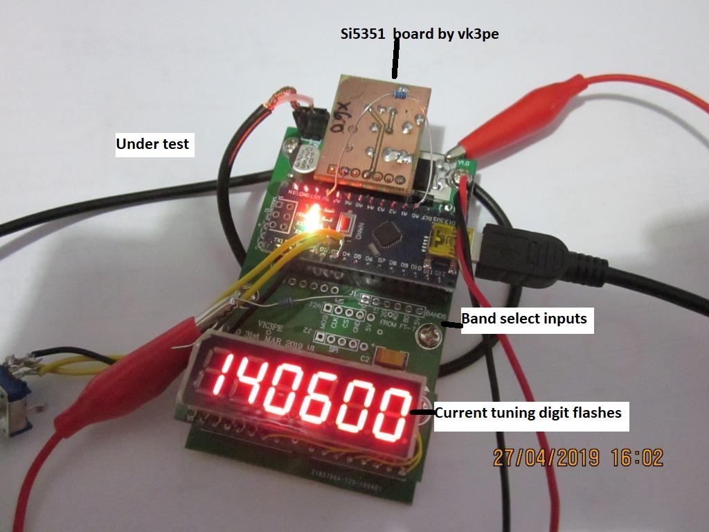
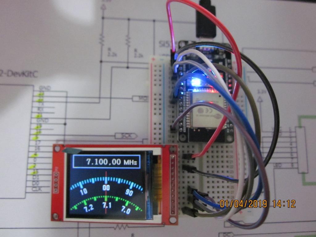
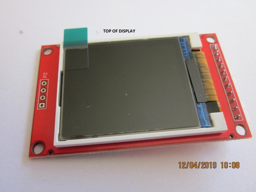
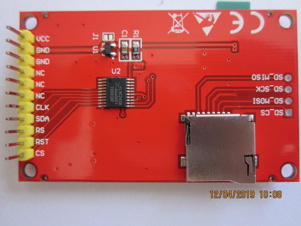
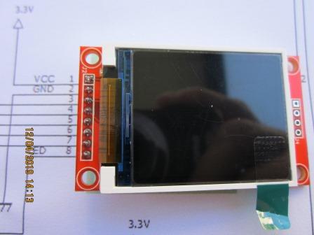
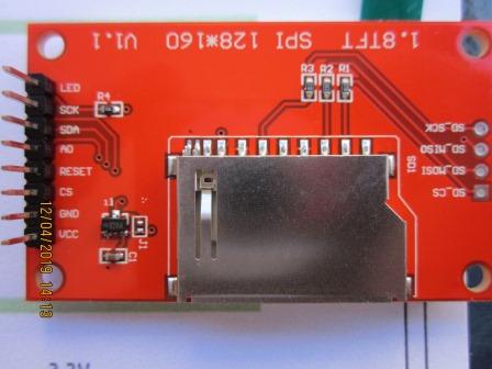
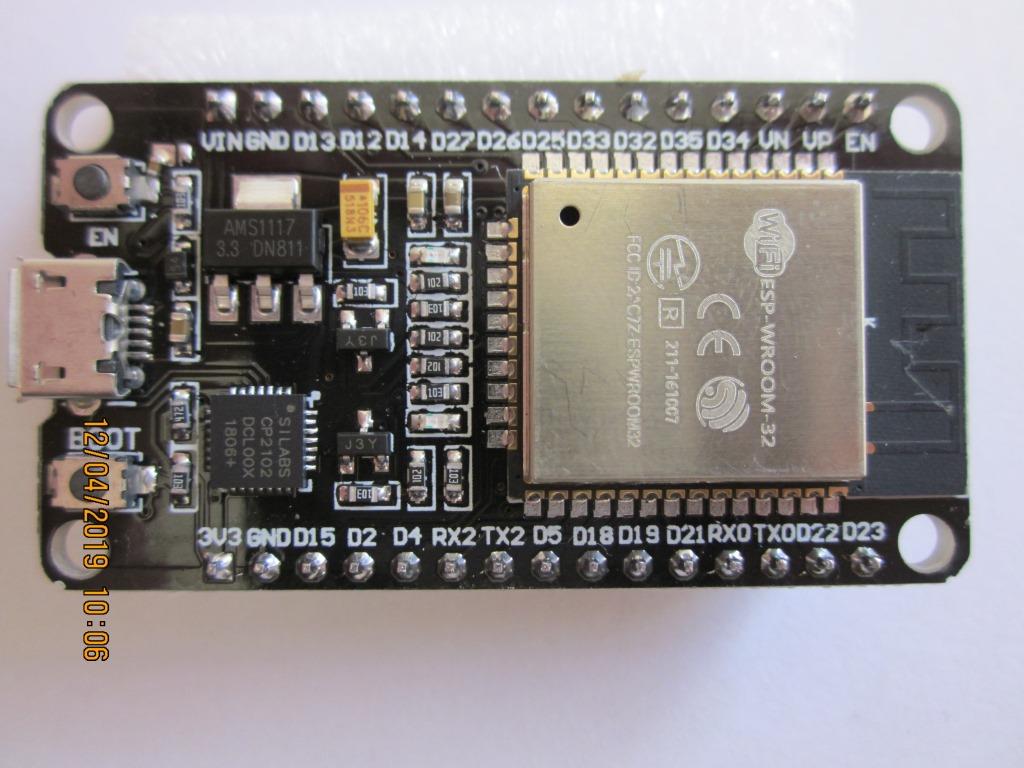
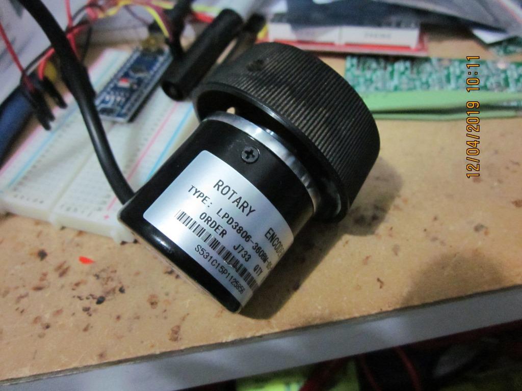
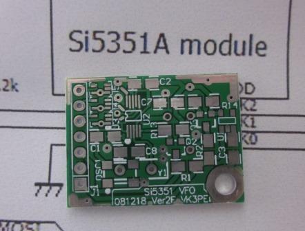
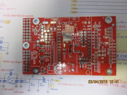
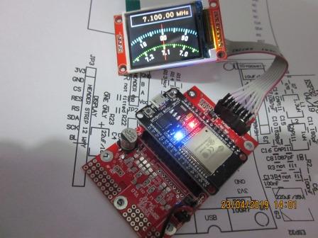
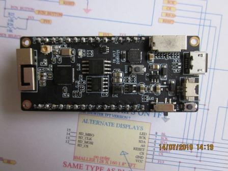
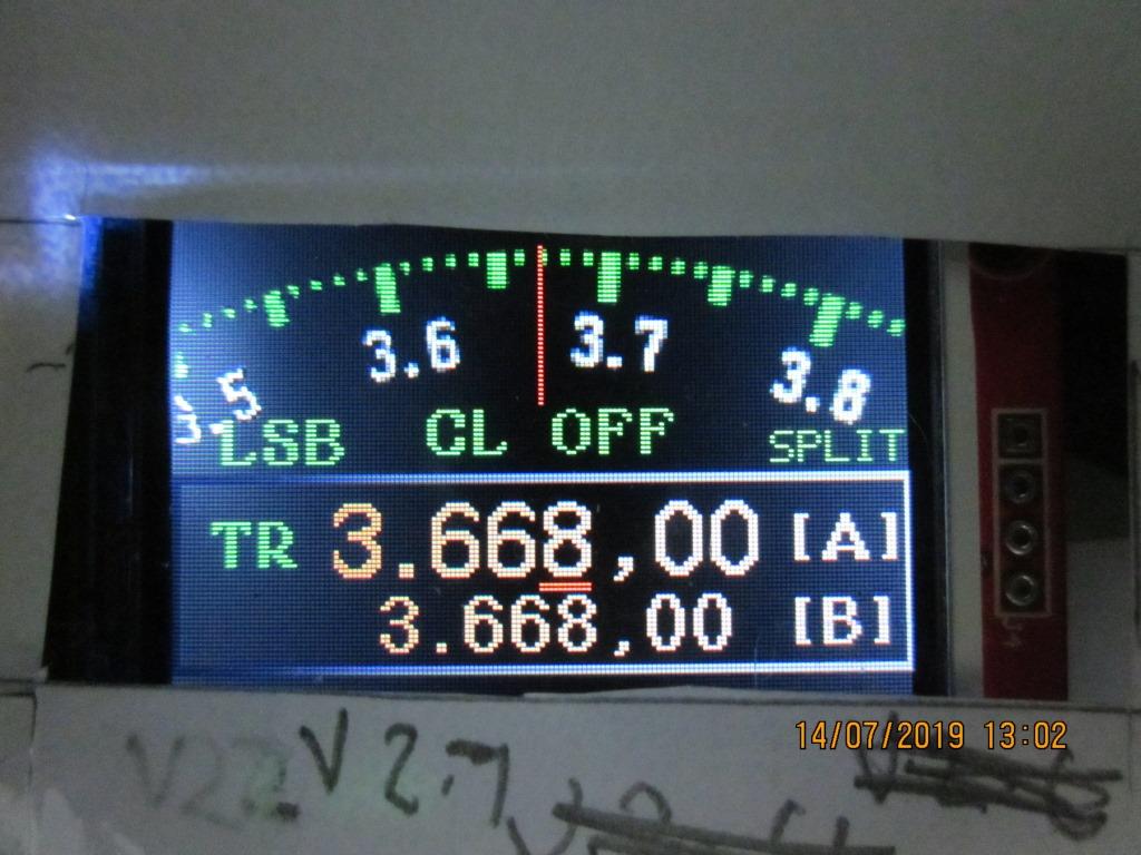
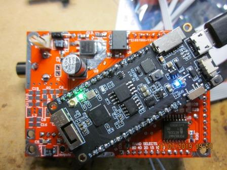
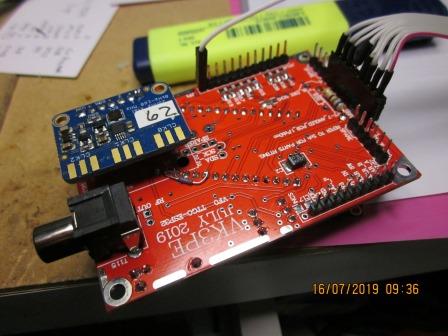
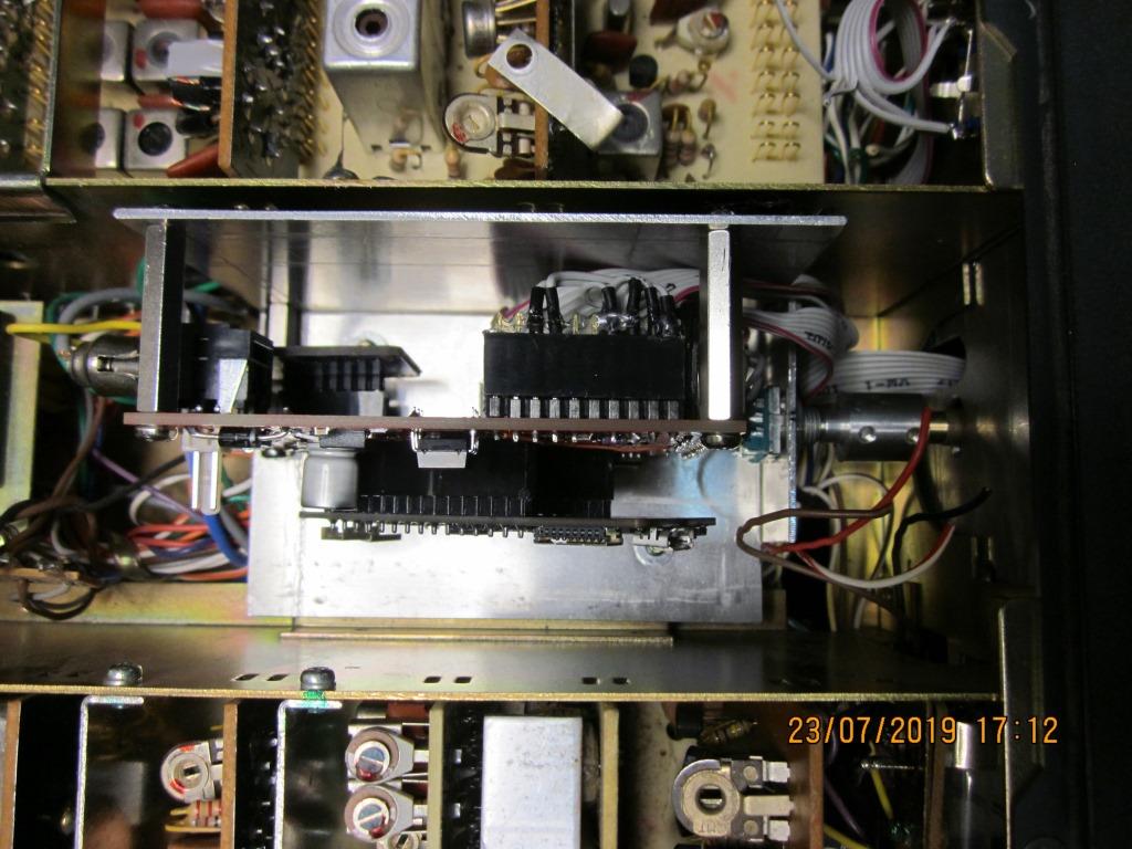
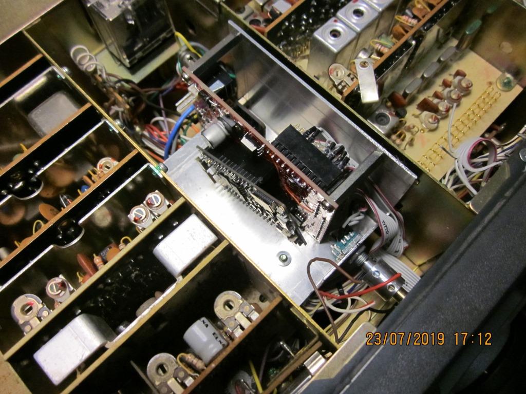
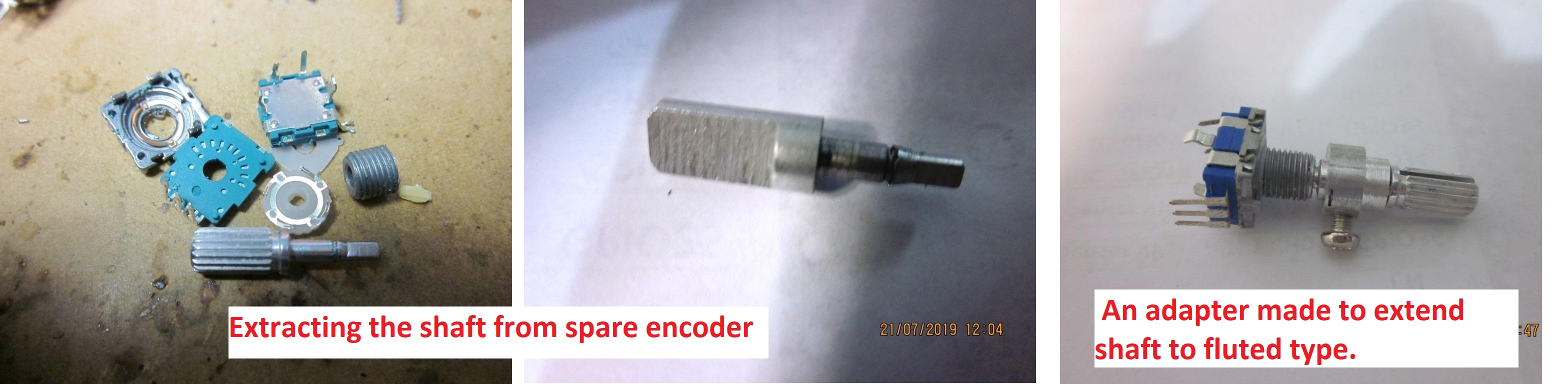
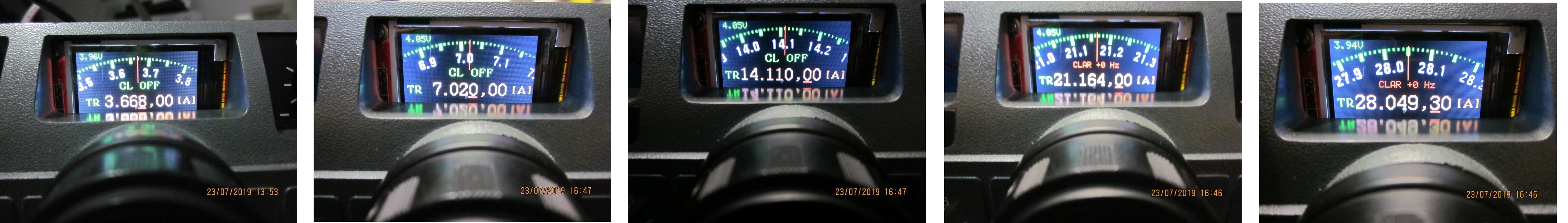
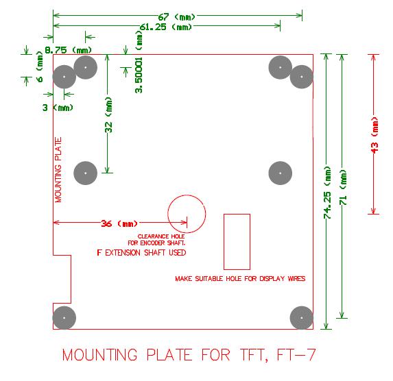 Plate width is 70mm
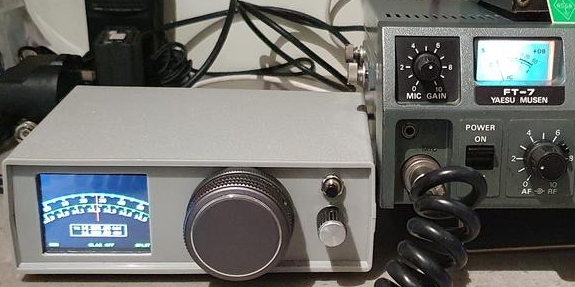